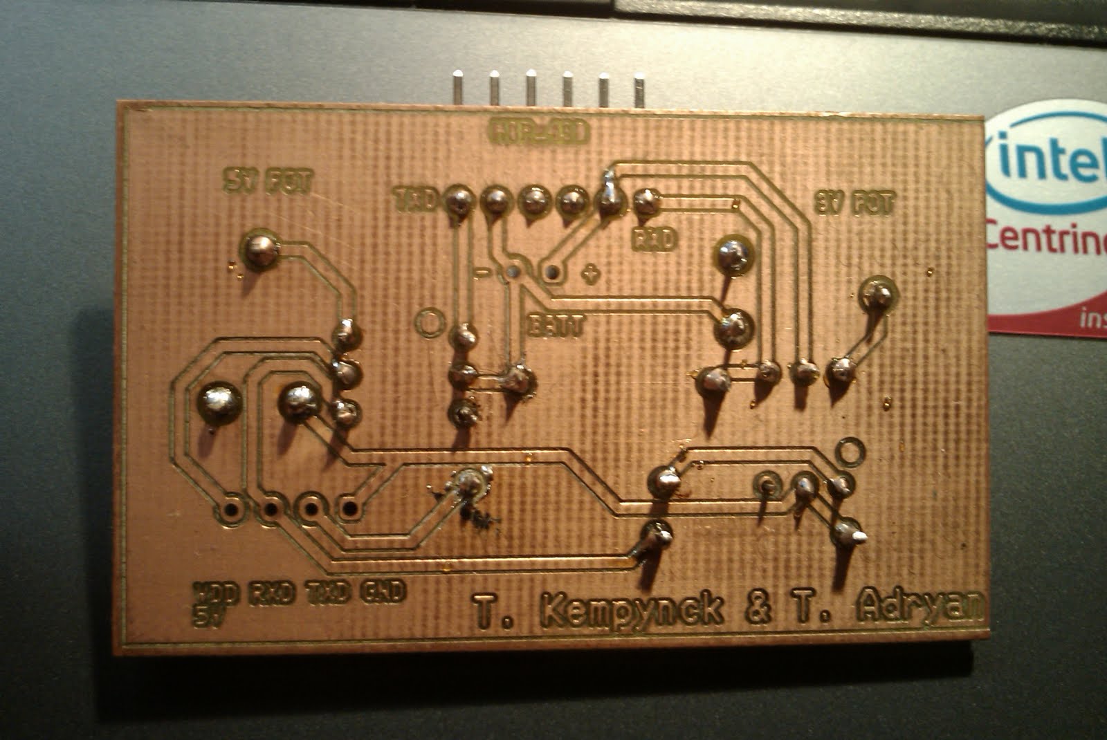
Today I soldered our circuit board and tom worked on the software for the msp 430.
It was the circuit board that we use to convert the 5V signal from the ELM327 to the 3,3V signal of the MSP430.
The pictures below show the circuit board.
donderdag 3 juni 2010
project session 31/05/2010
Serial obd2 communication
Since there was no project session last week we decided to get together an extra time.
That happened yesterday. Finally we had some success with our attempt to communicate with the OBD-2 bus. We could get a accurate reading for the engine RPM, the vehicle speed, engine load,coolant temperature and absolute throttle position.
We also got the software working on the msp430 it was only the software to write to the computer but it worked. we where able to send "hello world" to the pc.
Here is a picture of hyper terminal after executing the program on the msp.
woensdag 19 mei 2010
project session 17/05/2010
This time I designed the circuit board. Later on I will post pictures and the schematic.
Tom tested the hyper-terminal because it did not work last time with 2 example programs that where included in the EZ430-RF2500 experimental kit.
The first one was an UART echo with a baud-rate of 115200 and the second was an RX/TX UART with a baud-rate of 9600. This also failed with hyper terminal. After that he combined the 2 programs but it did not work. We asked the teacher for help he also did not see what was wrong, he said he would send us an example program. We are still waiting for that. So the biggest problem is that we can not test or simulate any program.
project session 10/05/2010
During this session I designed the schematic that enables the communication between the ELM chip and the MSP430, because the ELM-signal is on 5V and the MSP430's signal is on 3V.
We used optocouplers to change the signal to the right level.
This time Tom tried to test the software with hyper-terminal witch failed. He also tried to make changes to the software but it failed to.
project session 3/05/2010
Today we worked on the hardware, I soldered very thin wires to the PCB of the ELM board in order to get the RS232 coded signal before it gets to the RS232-to-USB-converter.
This wasn't easy it took me whole the session to complete that.
This time Tom added the UART communication part to the program.
woensdag 28 april 2010
project session 26/04/2010
Today I only worked on the hardware and I was searching for the hex dump of the ELM327.
I found out that the signal was a 5V signal, although I could only get the rising edge of the signal on the oscilloscope. The search for the hex file was unsuccessful but since the device that we use is a cheap china clone we may be able to read out the pic that is used instead of the ELM327 in order to make a circuit board dedicated for our project.
Tom did the software this time, he made some major advance for the software.
So we are on a good way to getting the job done.
Get together 24/04/2010
Today we booked some advance for our software (since we got the software working last time).
We finally could kind of prototype some self written software for the msp 430.
We also discovered that there maybe is a problem for the transmission from the elm327 to the msp430 since the signal voltage for the msp430 may only be 3,3V and the ELM327 probably sends 5V signals.
dinsdag 27 april 2010
project session 19/04/2010
This project session we finally booked some advance now we kind of know what way we are going.
We got it to work on a school computer tomorrow (20/04 we are going to get together to do some experiments with some hardware.
woensdag 10 maart 2010
eight project session 9/03/2010 (last for this trim.)
This project session we booked no advance at all in the last week we tried allot of things such as installing different drivers and software.
We also tried it with VM ware witch also did refuse to do the job. Whereas another group that has a similar project with the Msp 430 could get it working with VM ware.
So we are a bit desperate now. Tom and I both have Vista (which refuses to work with the msp 430) , our parents both got laptops with Windows xp but they are not always accessible for us, so this is now option.
Maybe we are able to come up with something after the exams.
donderdag 4 maart 2010
seventh project session 2/03/2010
During the seventh project session we are finally getting to write our own software for the msp430.
Unfortunately it appears to be that the kickstart software isn't fully supporting windows vista.
So we can read and edit .C files but we can not upload it to the msp430 itself.
So we have to use another laptop in order to get it working. Until now we did not solve this problem we have to use some older windows XP computer or we have to do a dual-boot my laptop witch I would not like to do.
I hope we can address this issue till the next project session.
woensdag 24 februari 2010
Sixth project session 23/02/2010
During this project session we were getting closer to understanding how the MSP430 sofware works.
In the previous post we mentioned an article from Elektor, for the project discussed in that article they used standard software libraries from Texas instruments.
There is a pdf file with that libraries that tells you quiet allot about how whole the software is put together.
You can find this file here:
http://focus.ti.com/lit/an/slaa325a/slaa325a.pdf
There is a link to the software libraries within the pdf file.
It won't take long until we can upload our first piece of software.
woensdag 10 februari 2010
forth and fifth project session 5/02 - 09/02/2010
This project sessions we tried to figure out how the software works.
On the Texas Instruments website there are several software demo's free to download.
But meanwhile we heard about an article from Elektor that was about the msp430 and the eZ430-RF2500.
It was in the November magazine of 2008.
That project looks simpler, so we decided that we first figure this one out.
Here is the link to the Elektor page:
http://www.elektor.nl/artikelen-als-pdf/2008/november/afstandsbediening-voor-rgb-led-sfeerverlichting.711148.lynkx
Some other intresting links:
http://focus.ti.com/docs/toolsw/folders/print/ez430-rf2500.html
(Video) http://e2e.ti.com/videos/m/microcontroller/97537.aspx
http://focus.ti.com/docs/toolsw/folders/print/iar-kickstart.html
dinsdag 26 januari 2010
Third project session 26/01/10
Today we had our Third project session, we had to hand in our paperwork as i said in our previous post.
Today we also heard that we maybe can get a OBD-2 to RS-232 for free, but we still not know if there is an interface with it, maybe we know more tomorrow.
maandag 25 januari 2010
The paperwork
The last two days we finished our paperwork. That we have to hand in tomorrow.
It is not at all easy to foresee everything when you hardly know how all the hardware works.
But we made it, everything has it's schedule and the major risks are foreseen and the tasks are divided.
woensdag 20 januari 2010
second project session 19/01/10
Today we mainly did the paperwork for the project.
We selected a project leader, Tom Kempynckis was chosen for this job.
Later on we will post some of the intresting paper work on here.
We also had concerns about the data rates and latency.
The wireless system that we are using is zigbee at 2.4GHz.
So we have a data rate of 250 kb/s to count on and a latency of 16ms.
This was what we have no, what do we need?
Since we are working with obd-2 there are 5 different protocols and all have very different secifications.
Any given vehicle will likely only implement one of the protocols. Often it is possible to make an educated guess about the protocol in use based on which pins are present on the J1962 connector:
- SAE J1850 PWM (pulse-width modulation - 41.6 kB/sec, standard of the Ford Motor Company)
- pin 2: Bus+
- pin 10: Bus–
- High voltage is +5 V
- Message length is restricted to 12 bytes, including CRC
- Employs a multi-master arbitration scheme called 'Carrier Sense Multiple Access with Non-Destructive Arbitration' (CSMA/NDA)
- SAE J1850 VPW (variable pulse width - 10.4/41.6 kB/sec, standard of General Motors)
- pin 2: Bus+
- Bus idles low
- High voltage is +7 V
- Decision point is +3.5 V
- Message length is restricted to 12 bytes, including CRC
- Employs CSMA/NDA
- ISO 9141-2. This protocol has an asynchronous serial data rate of 10.4 kBaud. It is somewhat similar to RS-232, but that the signal levels are different, and that communications happens on a single, bidirectional line without extra handshake signals. ISO 9141-2 is primarily used in Chrysler, European, and Asian vehicles.
- pin 7: K-line
- pin 15: L-line (optional)
- UART signaling (though not RS-232 voltage levels)
- K-line idles high
- High voltage is Vbatt
- Message length is restricted to 12 bytes, including CRC
- ISO 14230 KWP2000 (Keyword Protocol 2000)
- pin 7: K-line
- pin 15: L-line (optional)
- Physical layer identical to ISO 9141-2
- Data rate 1.2 to 10.4 kBaud
- Message may contain up to 255 bytes in the data field
- ISO 15765 CAN (250 kBit/s or 500 kBit/s). The CAN protocol is a popular standard outside of the US automotive industry and is making significant in-roads into the OBD-II market share. By 2008, all vehicles sold in the US will be required to implement CAN, thus eliminating the ambiguity of the existing five signalling protocols.
- pin 6: CAN High
- pin 14: CAN Low
Note that pins 4 (battery ground) and 16 (battery positive) are present in all configurations. Also, ISO 9141 and ISO 14230 use the same pinout, thus the connector shape does not distinguish between the two.
When we look at the data rates of ISO 15765 CAN and SAE J1850 PWM the data rate af our "medium" Zigbee is not sufficient.
So we will have to read the data of the OBD-2 via RS232.
Since OBD-2 to RS232 cables are widely and most likely used for this sort of applications we will use a cable like that.
The data rate of RS232 is 75 bits per second, so now we have plenty of speed provided by Zigbee.
dinsdag 19 januari 2010
first project session 12/01/10
Today we could try the wireless hardware a bit.
For the wireless transmission we are going to use eZ430-RF2500.
the hardware consists of a sender and a receiver, they look like this:
Sender with battery-pack:
reciever:
The eZ430-RF2500 is a complete wireless development tool for the MSP430 and CC2500 that includes all the hardware and software required to develop an entire wireless project with the MSP430 in a convenient USB stick. The tool includes a USB-powered emulator to program and debug your application in-system and two 2.4-GHz wireless target boards featuring the highly integrated MSP430F2274 ultra-low-power MCU. Projects may be developed and instantly deployed using the included battery expansion board and AAA batteries. All the required software is included such as a complete Integrated Development Environment and SimpliciTI, a propriety low-power star network stack, enabling robust wireless networks out of the box. The eZ430-RF2500 uses the MSP430F22x4 which combines 16-MIPS performance with a 200-ksps 10-bit ADC and 2 op-amps and is paired with the CC2500 multi-channel RF transceiver designed for low-power wireless applications.
The eZ430-RF emulator interface may be used with any Spy Bi-Wire enabled MSP430, such as the F22xx and F20xx series, and is fully compatible with the eZ430-F2013 and eZ430-T2012 target boards. The emulator interface can be used to download and debug your target applications, and can transmit serial data to your PC while in or out of a debug session.
Features
* CC2500 – 2.4 GHz, ISM band multi-channel low power transceiver
* 2 LEDs
* 1 pushbutton
* Supports development with all 2xx Spy Bi-Wire devices (MSP430F20xx, F21x2 & F22xx)
* Supports MSP430 Application UART allowing serial communication to PC
* Supports eZ430-T2012 and eZ430-RF2500T target boards
* Removable USB stick enclosure
* SimpliciTI, low power network stack
* Example wireless sensor network project measuring temperature, voltage and signal strength
woensdag 6 januari 2010
Some specifications
Underneath you can find an overview of different connectors as used for OBD-II diagnostic systems.
OBD-II Connector, J1962
Diagnostic connector (female) of the car:
| Pin-No. | Description |
|---|---|
| 1 | Manufacturer mandated |
| 2 | J1850 Bus+ |
| 3 | Manufacturer mandated |
| 4 | Car ground |
| 5 | Signal ground |
| 6 | CAN High (J-2284) |
| 7 | ISO 9141-2 K output |
| 8 | Manufacturer mandated |
| 9 | Manufacturer mandated |
| 10 | J1850 Bus |
| 11 | Manufacturer mandated |
| 12 | Manufacturer mandated |
| 13 | Manufacturer mandated |
| 14 | CAN Low (J-2284) |
| 15 | ISO 9141-2 L output |
| 16 | Battery (+) voltage |
Used pins of the connector shows kind of protocol:
| Pin (Signal) | Pin (Masse) | Pin (Signal) | Pin (Signal) | Pin (+12 V) | Protocol |
|---|---|---|---|---|---|
| -- | 4 + 5 | 7 | 15 *) | 16 | ISO 9141-2 |
| 2 | 4 + 5 | -- | 10 | 16 | PWM J1850 |
| 2 | 4 + 5 | -- | -- | 16 | VPW J1850 |
| -- | 4 + 5 | 6 | 14 | 16 | CAN Bus |
- *) Pin 15 only for older ISO 9141 implementations
- all other pins are manufacturer reserved and not used for standard OBD-II
Diagnostic connector (male) of diagnostic tool:
Contact usage of some manufacturers:
| Pin | SAE J1979, ISO 15031 | GM | Fiat | Opel | Saab | Isuzu | GM-LAN since 5.2002 |
|---|---|---|---|---|---|---|---|
| 1 | Manufacturer mandated | second UART | ABS, Brakes, K-Line | reserved | Saab Instruments (+) | SIR (GM8192 Prot.) | SW-LS-CAN (33kB) or DW-FT-CAN (+) (<125kb) |
| 2 | J1850 (+) PWM/VPW | J1850(+) VPW | DW-FT-CAN(+) | n/a | n/a | n/a | n/a |
| 3 | Manufacturer mandated | Comfort | Airbag | K-Line, K2, TCM, Sunroof, CDL, Multi-Timer | n/a | ABS (KW81-Prot.) | MS-CAN (+) (95kB) |
| 4 | Chassis ground | Chassis ground | Chassis ground | Chassis ground | Chassis ground | Chassis ground | Chassis ground |
| 5 | Signal ground | Signal ground | Signal ground | Signal ground | Signal ground | Signal ground | Signal ground |
| 6 | ISO 15765 HS-CAN (+) | PCM | ISO 15765 HS-CAN(+) | Blinkcode | Blinkcode | TCM | ISO 15765 HS-CAN (+) (500kB) |
| 7 | ISO 9141 K-Line | n/a | ISO 9141 K-Line (engine) | K-Line, K1 (engine) | K-Line, K1 (engine) | K-Linie, K1 (engine) | n/a |
| 8 | Manufacturer mandated | CCM | n/a | K-Line, K4 | K-Line (Saab 9000/1, KW81/82 Prot.) | n/a | reserved |
| 9 | Manufacturer mandated | first UART | Body ECU | reserved | Saab Instruments (-) | ECM/TCM (GM8192 Prot.) | DW-FT-CAN (-) (<125kb) |
| 10 | J1850 (-) PWM | n/a | DW-FT-CAN (-) | n/a | n/a | n/a | n/a |
| 11 | Manufacturer mandated | EVA Controller | (Anti-Theft system) | reserved | L-Line Memory Seats | SIR | MS-CAN (-) (95kB) |
| 12 | Manufacturer mandated | ABS | engine compartment | K-Line, K3, ABS, TC, Steering, RTD, OW | n/a | ABS | K-Line (KW82 Prot.) |
| 13 | Manufacturer mandated | SIR | Luggage compartment | reserved f. K-Line, K5 | n/a | ECM | reserved |
| 14 | ISO 15765 HS-CAN (-) | E&C | ISO 15765 HS-CAN (-) | reserved | n/a | n/a | ISO 15765 HS-CAN (-) (500kB) |
| 15 | ISO 9141 L-Line | n/a | n/a | n/a | n/a | n/a | n/a |
| 16 | Battery Plus, unswitched | Battery Plus, unswitched | Battery Plus, unswitched | Battery Plus, unswitched | Battery Plus, unswitched | Battery Plus, unswitched | Battery Plus, unswitched |
Internal contacting Patch-Connector OBD2/RJ45
OBD-II (male) / RJ45 female
| OBD-II Pin | Description | RJ45-Pin |
|---|---|---|
| 2 | J1850 Bus+ | 6 |
| 4, 5 | Ground | 1 |
| 6 | CAN-Bus | 7 |
| 7 | ISO 9141-2 K-output | 4 |
| 10 | J1850 Bus | 3 |
| 14 | CAN-Bus | 8 |
| 15 | ISO 9141-2 L-output | 5 |
| 16 | Battery +12V | 2 |
OBD-II (female) / RJ45 female
| OBD-II Pin | Description | RJ45-Pin |
|---|---|---|
| 2 | J1850 Bus+ | 6 |
| 4, 5 | Ground | 1 |
| 6 | CAN-Bus | 7 |
| 7 | ISO 9141-2 K-output | 4 |
| 10 | J1850 Bus | 3 |
| 14 | CAN-Bus | 8 |
| 15 | ISO 9141-2 L-output | 5 |
| 16 | Battery +12V | 2 |
OBD-II Cabel connection (for interfaces)

|
The start
This blog is part of a school project as a reflection of our progress.
Tom Kempynck and me Tobias Adryan are going to make a Wireless obd signal analyzer
With that device you will be able to see a live feed of the sensors in your car.
This will happen via the OBD-2 bus. Which in Europe is an obligated bus for all petrol cars since 2001 and for all diesels since 2003. Nearly every car that is made the last 10 years has a bus like that because it was earlier obligated for every car in the United states and Japan.
Some more interesting information about OBD and its history can be found here:
http://en.wikipedia.org/wiki/On-board_diagnostics#OBD-II
Some more technical specifications about OBD-2 can be found here:
http://www.obdii.com/
Abonneren op:
Posts (Atom)