Today I soldered our circuit board and tom worked on the software for the msp 430.
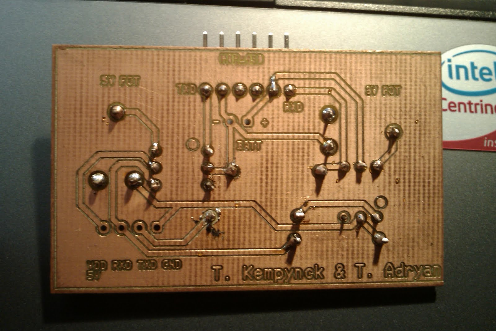
It was the circuit board that we use to convert the 5V signal from the ELM327 to the 3,3V signal of the MSP430.
The pictures below show the circuit board.
donderdag 3 juni 2010
project session 31/05/2010
Serial obd2 communication
Since there was no project session last week we decided to get together an extra time.
That happened yesterday. Finally we had some success with our attempt to communicate with the OBD-2 bus. We could get a accurate reading for the engine RPM, the vehicle speed, engine load,coolant temperature and absolute throttle position.
We also got the software working on the msp430 it was only the software to write to the computer but it worked. we where able to send "hello world" to the pc.
Here is a picture of hyper terminal after executing the program on the msp.
woensdag 19 mei 2010
project session 17/05/2010
This time I designed the circuit board. Later on I will post pictures and the schematic.
Tom tested the hyper-terminal because it did not work last time with 2 example programs that where included in the EZ430-RF2500 experimental kit.
The first one was an UART echo with a baud-rate of 115200 and the second was an RX/TX UART with a baud-rate of 9600. This also failed with hyper terminal. After that he combined the 2 programs but it did not work. We asked the teacher for help he also did not see what was wrong, he said he would send us an example program. We are still waiting for that. So the biggest problem is that we can not test or simulate any program.
project session 10/05/2010
During this session I designed the schematic that enables the communication between the ELM chip and the MSP430, because the ELM-signal is on 5V and the MSP430's signal is on 3V.
We used optocouplers to change the signal to the right level.
This time Tom tried to test the software with hyper-terminal witch failed. He also tried to make changes to the software but it failed to.
project session 3/05/2010
Today we worked on the hardware, I soldered very thin wires to the PCB of the ELM board in order to get the RS232 coded signal before it gets to the RS232-to-USB-converter.
This wasn't easy it took me whole the session to complete that.
This time Tom added the UART communication part to the program.
woensdag 28 april 2010
project session 26/04/2010
Today I only worked on the hardware and I was searching for the hex dump of the ELM327.
I found out that the signal was a 5V signal, although I could only get the rising edge of the signal on the oscilloscope. The search for the hex file was unsuccessful but since the device that we use is a cheap china clone we may be able to read out the pic that is used instead of the ELM327 in order to make a circuit board dedicated for our project.
Tom did the software this time, he made some major advance for the software.
So we are on a good way to getting the job done.
Get together 24/04/2010
Today we booked some advance for our software (since we got the software working last time).
We finally could kind of prototype some self written software for the msp 430.
We also discovered that there maybe is a problem for the transmission from the elm327 to the msp430 since the signal voltage for the msp430 may only be 3,3V and the ELM327 probably sends 5V signals.
Abonneren op:
Posts (Atom)